
(1).png")
MaxBand® WideBand OM5 Bending Insensitive Multimode Fibre
Classification:
MaxBand® WideBand OM5 Bending Insensitive Multimode Fibre is a 50µm laser-optimized multimode fibre designed for short wavelength division multiplexing (SWDM) applications.
Cotnact:
Details Introduction
MaxBand® WideBand OM5 Bending Insensitive Multimode Fibre is a 50µm laser-optimized multimode fibre designed for short wavelength division multiplexing (SWDM) applications. Unlike legacy OM4 multimode fibre with high bandwidth at 850nm, MaxBand® OM5 Bending Insensitive Multimode Fibre has high bandwidth in the 850 nm - 950 nm window and maintaining backward compatiblity with legacy OM4 fibre. WideBand OM5 and multi-wavelength transceivers are a viable solution for 100Gb/s and 400Gb/s multi-wavelength systems. MaxBand® WideBand OM5 Bending Insensitive Multimode Fibre complies with or exceeds ISO/IEC 11801-4 OM5 specification, IEC 60793-2-10 A1-OM5 specification, and TIA-492AAAF A1-OM5 specification.
|
Features |
Benefits and Applications |
|
Designed for multi-wavelength systems High bandwidth in the wavelength range of 850 nm - 950 nm Backward compatiblity with legacy OM4 fibre |
Support single-wavelength and multi-wavelength transmission system from 40 Gb/s to 400 Gb/s |
|
Superior geometry uniformity Low attenuation High bandwidth Low differential mode delay (DMD) |
Data centers Data storage networks High-performance computing centers a Office centers Local area networks (LAN) |
|
Very low macro-bending sensitivity |
Supports the use and installation of optical cables with a small bending radius |
|
Coated with YOFC's proprietary dual layer UV curable acrylate |
High resistance to micro-bending Optimized performance in tight-buffer cable applications Stable performance over a wide range of environmental conditions |
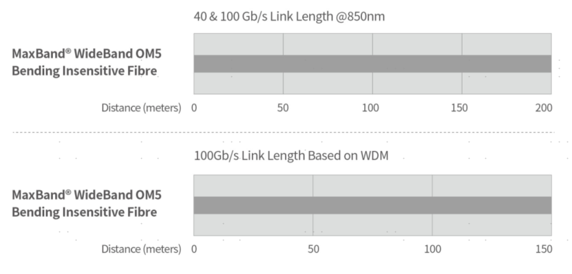
System Link Length
Parameter
|
Characteristics |
Conditions |
Specified values |
Units |
|
|
Geometry Characteristics |
||||
|
Core Diameter |
-- |
50±2.5 |
[μm] |
|
|
Core Non-Circularity |
-- |
≤5.0 |
[%] |
|
|
Cladding Diameter |
-- |
125.0±1.0 |
[μm] |
|
|
Cladding Non-Circularity |
-- |
≤0.6 |
[%] |
|
|
Coating Diameter |
-- |
245±7 |
[μm] |
|
|
Coating/Cladding Concentricity Error |
-- |
≤10.0 |
[μm] |
|
|
Coating Non-Circularity |
-- |
≤6.0 |
[%] |
|
|
Core/Cladding Concentricity Error |
-- |
≤1.0 |
[μm] |
|
|
Delivery Length |
-- |
up to 8.8 |
[km/reel] |
|
|
Optical Characteristics |
||||
|
Attenuation |
850nm |
≤2.4 |
[dB/km] |
|
|
953nm |
≤1.7 |
[dB/km] |
||
|
1300nm |
≤0.6 |
[dB/km] |
||
|
Overfilled Modal Bandwidth |
850nm |
≥3500 |
[MHz·km] |
|
|
953nm |
≥1850 |
[MHz·km] |
||
|
1300nm |
≥500 |
[MHz·km] |
||
|
Effective Modal Bandwidth |
850nm |
≥4700 |
[MHz·km] |
|
|
953nm |
≥2470 |
[MHz·km] |
||
|
Application support distance on |
-- |
-- |
-- |
|
|
100Gb/s WDM1 |
-- |
150 |
[m] |
|
|
40Gb/s WDM1 |
-- |
440 |
[m] |
|
|
40GBASE-SR4 / 100GBASE-SR102 |
850nm |
200 |
[m] |
|
|
Numerical Aperture |
-- |
0.200±0.015 |
-- |
|
|
Group Refractive Index |
850nm |
1.482 |
-- |
|
|
1300nm |
1.477 |
-- |
||
|
Zero Dispersion Wavelength(λ0) |
-- |
|
[nm] |
|
|
Zero Dispersion Slope(S0) |
-- |
≤4(-103)/(840(λ0/840)4) |
[ps/(nm2·km)] |
|
|
Macrobending Loss3 |
-- |
@850nm |
@1300nm |
-- |
|
2 Turns @ 15 mm Radius |
-- |
≤0.1 |
≤0.3 |
[dB] |
|
2 Turns @ 7.5 mm Radius |
-- |
≤0.2 |
≤0.5 |
[dB] |
|
Backscatter Characteristics |
850nm & 1300nm |
|
||
|
Step(Mean of Bidirectional Measurement) |
-- |
≤0.10 |
[dB] |
|
|
Irregularities Over Fibre Length and Point Discontinuity |
-- |
≤0.10 |
[dB] |
|
|
Attenuation Uniformity |
-- |
≤0.08 |
[dB/km] |
|
|
Environmental Characteristics |
850nm & 1300nm |
|
||
|
Temperature Cycling |
at -60℃ to 85℃ |
≤0.10 |
[dB/km] |
|
|
Temperature-Humidity Cycling |
at -10℃ to 85℃ and 4% to 98% RH |
≤0.10 |
[dB/km] |
|
|
Water Immersion |
at 23℃ for 30 days |
≤0.10 |
[dB/km] |
|
|
Dry Heat |
at 85℃ for 30 days |
≤0.10 |
[dB/km] |
|
|
Damp Heat |
at 85℃ and 85% RH for 30 days |
≤0.10 |
[dB/km] |
|
|
Mechanical Specification |
||||
|
Proof Test |
-- |
≥9.0 |
[N] |
|
|
-- |
≥1.0 |
[%] |
||
|
-- |
≥100 |
[kpsi] |
||
|
Coating Strip Force |
typical average force |
1.5 |
[N] |
|
|
peak force |
≥1.3, ≤8.9 |
[N] |
||
|
Dynamic Stress Corrosion Susceptibility Parameter(nd, typical) |
-- |
20 |
-- |
|
Remarks:
1. Support distance with SWDM transceivers http://www.swdm.org/msa/
2. Support distances considering maximum cable attenuation of 3.0 dB/km at 850 nm, maximum total splice/connector loss of 1.0 dB and VCSELs maximum RMS spectral width ≤ 0.45 nm.
3. The launch condition for the macrobending loss measurement fulfils that described in lEC 61280-4-1.
Documents
Next Page
Keyword:
MaxBand® WideBand OM5 Bending Insensitive Multimode Fibre
Production


Related Products
Message consultation
We will surprise you with a gift as soon as we receive your message.
Contact Information
Add: 9th Floor, Building B, Optics Valley Times Square, No. 111 Guanshan Avenue, Donghu New Technology Development Zone, Wuhan


